In a lot of technical environments there is the need for a Trivial File Transfer Protocol, or in short, TFTP server. TFTP is a simpel file transfer protocol that is readily used to boot systems over a network, or to upload or download configuration files from systems as routers, switches, firewalls, and so on …
The installation procedure of the below tftp server was performed on a Debian Stretch system with tftp-hpa as the daemon. The daemon would allow read and write operations. Subsequently, a Git script is installed as a systemd service to auto commit changes to a Git repository for history purposes. An instance of Gitlab was used as the Git server to store the Git repository.
TFTP Daemon Configuration
$ apt-get install -y tftpd-hpa
$ vi /etc/default/tftpd-hpa
First create a git repository in Gitlab, and note the url from your repository. Thereafter, create a Gitlab personal access token, this is required to access the repository later on.
$ git clone https://mygitlab.myhome.com/mysmartproject.git /srv/tftproot
$ git config --global credential.helper store /root/.git-credentials
# -- enter 'git' as username, and your token as the password
$ git pull
Install gitwatch as a service:
$ sudo vi /etc/systemd/system/gitwatch.service
[Unit]
Description=Watch file or directory and git commit all changes
After=network.target

[Service]
User=root
ExecStart=/usr/local/bin/gitwatch -r origin -b master /srv/tftproot
ExecStop=/bin/true

[Install]
WantedBy=multi-user.target
Install PuTTY, PuTTYgen, And Pageant on your Windows system
First we need to install PuTTY, PuTTYgen, and Pageant on our Windows system. All we need to do is download the exectuable files (.exe) and save them somewhere, e.g. on the desktop. We don’t need to install them as they are standalone applications. To start them, we only need to double-click them.
Download the following files from the PuTTY download page and save them on your Windows system, e.g. on the desktop:
In PuTTY, you can create profiles for connections to your various SSH servers, so you don’t have to type in the settings again when you want to connect to a certain server again.
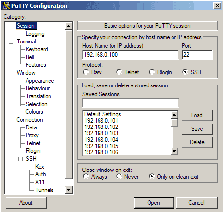
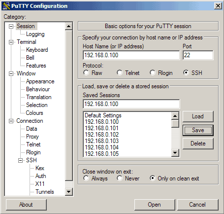
Let’s create a profile for our 192.168.0.100 server. Start PuTTY by double-clicking its executable file. You are now in the category Session (see the tree on the left side of the screenshot). Enter 192.168.0.100 under Host Name (or IP address), enter 22 under Port and select SSH under Protocol:
Then go to Connection -> Data and specify the username with that you want to log in to your SSH server under Auto-login username. In this article I use root:
Then go to Session again. Under Saved Sessions enter a name for the profile, e.g. 192.168.0.100 or any other string that lets you remember for which server the profile is. Then click on Save:
The next time you use PuTTY, you can simply select the appropriate profile from the Saved Sessions text area, click on Load and then Open.
Now we can connect to our SSH server simply by clicking on Open.
If you connect to the server for the first time, a security warning pops up. This is because PuTTY doesn’t know the server’s host key yet, so it is safe to click on Yes. (If this happens again later on, this can mean that another server is now running under the same IP address, or that someone has broken in and changed the key.)
We have saved the username with which we connect in our profile settings, so we don’t have to type it here again. We only have to specify that user’s password:
Generate A Private/Public Key Pair
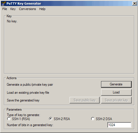
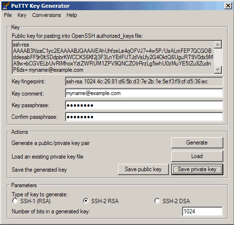
We can use PuTTYgen to create a private/public key pair. Start it by double-clicking its executable file. Make sure you select SSH-2 RSA under Type of key to generate and specify 1024 as the Number of bits in a generated key. Then click on Generate:
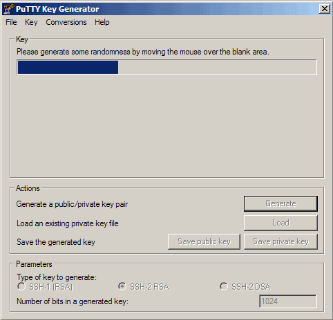
Please move the mouse pointer over the blank area during the key generation to generate some randomness:
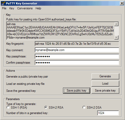
Now a private/public key pair has been generated. Under Key comment, you can enter any comment; normally you use your email address here. Then specify a Key passphrase and repeat it under Confirm passphrase. You’ll need that passphrase to log in to SSH with your new key. Then click on Save publick key and save it in some safe location on your computer. You are free to choose a filename and extension, but it should be one that lets you remember for which system it is.
Then click on Save private key. You can save it in the same location as the public key – it should be a location that only you can access and that you don’t lose! (If you lose the keys and have disabled username/password logins, then you can’t log in anymore!) Again, you’re free to choose a filename, but this time the extension must be .ppk:
Then copy the public key from the PuTTYgen window:
Save The Public Key On The Server
Then log in to your SSH server (if you have closed the previous SSH session already), still with the username and password, and paste the public key into the file ~/.ssh/authorized_keys2 (in one line!) like this:
mkdir ~/.ssh
chmod 700 ~/.ssh
vi ~/.ssh/authorized_keys2
# now paste your ssh key in this file and save it
That file mustbe write/readable only by that user, so we run
chmod 600 ~/.ssh/authorized_keys2
Attach The Private Key To The PuTTY Profile
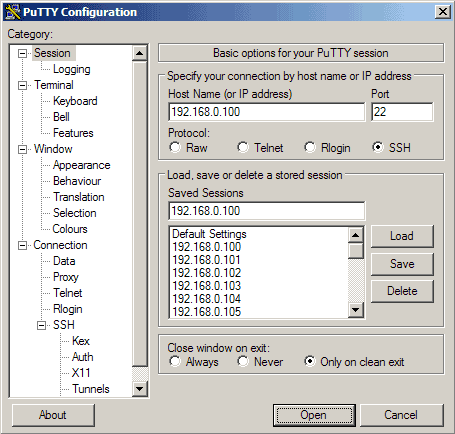
Now launch PuTTY again and load the profile of your SSH server (192.168.0.100):
Then go to SSH -> Auth and click on Browse:
Browse your file system and select your previously created private key:
Then go to Session again and click on Save:
Now we have attached the private key to our 192.168.0.100 PuTTY profile.
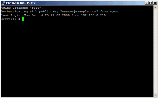
Our First Key-Based Login
Now everything is ready for our first key-based login to our SSH server. Click on Open:
As you can see, the public key is now used for authentication, and you are asked for the passphrase:
Disable Username/Password Logins
Up to now, you can log in with your private/public key pair and still with username/password logins, so if someone doesn’t attach a private key to his PuTTY session, he will be asked for a username and password. So to achieve a better security, we must disable the username/password logins (you should do this only when you know that your key-based logins are working, because if they aren’t and you disable username/password logins, then you have a problem…).
To disable the username/password logins, we must modify the sshd configuration file. On Debian/Ubuntu systems, it’s /etc/ssh/sshd_config. You should set Protocol to 2 (1 is insecure and should not be used!), PasswordAuthentication to no, and UsePAM to no (or comment out the UsePAM line), e.g. like this:
vi /etc/ssh/sshd_config
[...]
Protocol 2
PasswordAuthentication no
UsePAM no
[...]
Then restart sshd. On Debian/Ubuntu, you can do it like this:
/etc/init.d/ssh restart
Now if you open a PuTTY session without your private key attached, you shouldn’t be able to log in anymore.
Let Pageant Remember Your Key Passphrase
Whenever you use your key-based login now, you still have to specify your key passphrase. This can be annoying if you connect to the SSH server multiple times a day. Fortunately, you can tell the passphrase to Pageant which will then provide the passphrase whenever you log in to your SSH server.
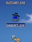
You can start Pageant by double-clicking its executable file, afterwards, you should see Pageant running in the taskbar:
Now double-click the Pageant icon in the taskbar. The following window comes up. Click on Add Key:
Browse your filesystem and select your private key:
Then enter the passphrase for the private key:
The key is now listed in Pageant’s key list. Click on Close:
As long as Pageant is running in the taskbar, you can log in to your SSH server without providing the passphrase – this is done by Pageant:
When you stop Pageant, it forgets all keys, so the next time you start Pageant you must add the keys again. This can also be annoying, but to prevent this, we can create a shortcut on the desktop to the Pageant executable. Right-click the Pageant executable and select Create Shortcut.
You should now find a shortcut. Right-click it and go to Properties.
Under Target, you will now find the path to pageant.exe, e.g. “C:\Users\SomeUser\Desktop\pageant.exe” (if there are no spaces in your path, you don’t need the quotation marks). You can now simply add the location of your private key to that line, for example if you private key is C:\putty\my_keys\private_key_192.168.0.100.ppk then the line should look like this:
if there are spaces in the path to your private key, you must wrap it in quotation marks again, e.g. like this:
“C:\Users\SomeUser\Desktop\pageant.exe” “C:\directory with lots of spaces in name\my keys\private_key_192.168.0.100.ppk”
Now when you double-click on the Pageant shortcut, Pageant will automatically load your private key and ask you for the passphrase. Enter it, and that’s it.
The Raspberry Pi is a cost effective SBC, which can be used for various internet-of-things purposes. I have been using 5 RPi’s as a camera solution with motion detection and post-processing. This application requires high reliability and it was a pretty long journey until all off the issues were solved. I am sharing the facts I have learned here, in the hope it will benefit other people in the attempt to attain stability on the Raspberry Pi.
1. Connectivity
The first thing you need is proper connectivity. At first this seemed easy, just use a WiFi USB-Key, set up wpa_supplicant, and you’re done. Guess not. There are many WiFi USB-Key’s on the market, but not all of them are supported under Linux. To be able to choose a working adapter, it’s advisable to take a look at the wireless wiki of kernel.org. Not all chipset manufacturers have open firmware for their products, limiting their usage in open source systems. So make sure to choose a listed chipset, for which there is open firmware, and a compatible driver, based on that, select an appropriate adapter.
For places where signal quality is low, it can be beneficial to connect an external antenna, this will amplify the reception of your wireless adapter by a few db, which sometimes makes a difference in good, bad, or ugly communication.
In my case, I was suffering from intermittent disconnections. To overcome this, I wrote a small script which would bring the connection back up when it failed.
The Raspberry Pi’s which I was configuring were not going to have a public IP address, nor was there any port forwarding installed on the remote end firewall for direct SSH access. Therefore I configured a reverse shell script which would perform a dial out to another SSH server under my control, and set up an SSH tunnel (reverse port forwarding).
Once the script was in place I still needed to install a service file to make it start automatically.
$ sudo vi /etc/init.d/sshtunnel
#! /bin/sh

### BEGIN INIT INFO
# Provides:             sshtunnel
# Required-Start:       $remote_fs $syslog
# Required-Stop:        $remote_fs $syslog
# Default-Start:        2 3 4 5
# Default-Stop:
# Short-Description:    SSH Tunnel
### END INIT INFO

set -e

export PATH="${PATH:+$PATH:}/usr/sbin:/sbin"

. /lib/lsb/init-functions

case "$1" in
  start)
        log_daemon_msg "Starting SSH Tunnel" "sshtunnel" || true
        iwconfig wlan0 power off
        if start-stop-daemon --background --start --quiet --oknodo --pidfile /var/run/sshtunnel.pid --exec /usr/local/bin/sshtunnel.sh -- rpiuser\@yourhost 23 33 3302 ; then
            log_end_msg 0 || true
        else
            log_end_msg 1 || true
        fi
        ;;
  stop)
        log_daemon_msg "Stopping SSH Tunnel" "sshtunnel" || true
        if start-stop-daemon --stop --quiet --oknodo --pidfile /var/run/sshtunnel.pid; then
            log_end_msg 0 || true
        else
            log_end_msg 1 || true
        fi
        killall sshtunnel.sh &> /dev/null
        killall ssh &> /dev/null
        sleep 5
        ;;

  status)
        status_of_proc -p /var/run/sshtunnel.pid /usr/local/bin/sshtunnel sshtunnel && exit 0 || exit $?
        ;;
  *)
        log_action_msg "Unknown action!" || true
        exit 1
esac

exit 0
A startup script needs to be writeable, so make sure to change the permissions to make the startup script executable:
$ sudo chmod 755 /etc/init.d/sshtunnel
It’s possible that you will need to amend the script to fit for your set-up. Basically after each boot or WiFi re-connection, the Raspberry Pi connects to my own SSH server and starts a reverse port forwarding so I can access the Raspberry Pi from remote. The login from the Raspberry Pi to my own SSH server is configured for single-sign-on, or key based authentication, so the login process is automated and doesn’t require any user attention.
3. Bad SD card
To survive an unexpected power off, you need to have all file systems mounted read-only.
Make sure to purchase a decent quality SD card for your Raspberry Pi. These cards are not made for heavy write operations, that will break them after time.
4. Read-only filesystem
This is one of the most complicated things, but when done properly, it’s not too much work and it won’t cause any problems.
Unless you have special requirements, there are only a few paths which needs to be writable. So let’s go through all steps required to make a truly, trouble-free read-only RPi:
4.1 Update your RPi so you have the recent software
It’s a bad idea to set it up with an old software. That may complicate the update later…
4.2 Remove unnecessary services and files
Here is the command. Of course, remove only what you don’t need. But this is what you probably won’t need on a headless RPi. You definitely don’t want cron on your read-only RPi unless you have external hardware clock source, more about it later.
You won’t need normal syslog text files on a read-only filesystem, either. Install busybox syslog instad. It logs into memory and is very lightweight. You can then use logread command to read syslog ringbuffer from the memory when needed.
Because the filesystem will be mounted read-only, there is nothing to be corrupted so filesystem check must be disabled. I say MUST because it MUST. If you don’t have an external HW clock and use NTP time sync only and you do a change to the filesystem and reboot, filesystem check will see it as an update from the future, denying further boot, requiring manual action on the site. To disable filesystem checks, specifying ‘fastboot’ to the kernel cmdline should be enough. You also don’t want any swapfiles. You can disable them by specifying ‘noswap’ to the cmdline. So edit /boot/cmdline.txt and append the following two at the end of the line:
fastboot noswap
4.5 Set up clock sync.
Because you uninstalled fake-hwclock (it won’t be able to store clock on a readonly filesystem), you need to install and set up NTP sync. Also clock keeping is poor on a standard RPi so you may consider updating time regularly (every hour or two should be enough).
I used ntpdate for this. apt-get install ntpdate. I added it to /etc/rc.local:
/usr/sbin/ntpdate -b cz.pool.ntp.org # change the ntp server according to your location
4.6 Update some writable paths
Now you need to update a few services which writes something. wpa_supplicant for WiFi is ok as it already writes to /tmp. DHCP lease is the major problem. Simple solution is to delete the old directory and make it as a symlink to tmp like this:
rm -rf /var/lib/dhcp/
ln -s /tmp /var/lib/dhcp

You can consider adding more symlinks from some /var subdirectories, especially run,spool and lock
rm -rf /var/run /var/spool /var/lock
ln -s /tmp /var/run
ln -s /tmp /var/spool
ln -s /tmp /var/lock
4.7 Consider disabling some other startup scripts
insserv -r bootlogs
insserv -r sudo # if you plan to be root all the time
insserv -r alsa-utils # if you don't need alsa stuff (sound output)
insserv -r console-setup
insserv -r fake-hwclock # probably already removed at this point..
If you use alsamixer to set up volume level, make sure to do so in read-write filesystem. If won’t be able to store it on a readonly filesystem. It normally uses this path /var/lib/alsa/asound.state .
4.8 Tell the kernel to mount root filesystem read-only!
Finally getting there.. Add ” ro” at the end of your /boot/cmdline.txt line.
4.9. Add “,ro” flag to both block devices in /etc/fstab
…to let the system know you want to mount them read-only:
It is useful to set up a watchdog which can reboot your RPi in case it renders unresponsive, we can use a watchdog kernel module for this purpose.
Load the watchdog kernel module:
$ sudo modprobe bcm2708_wdog
Add bcm2708_wdog into the /etc/modules so it gets loaded on boot.
$ sudo echo "bcm2708_wdog" >> /etc/modules
In addition to the kernel module, there is also a userspace daemon that we need:
$ sudo apt-get install watchdog
Examine the configuration file: /etc/watchdog.conf and configure it as appropriate for your situation.
Uncomment the line watchdog-device = /dev/watchdog
Uncomment the line with max-load-1
Setting a minimum free RAM amount is a good idea. Before starting the watchdog service, be prepared that you might have configured it incorrectly and it will reboot immediately when you start it and may continuously reboot after each boot. So be prepared to modify your SD card on a different device if that happens.
Enable the watchdog to start at boot and start it now:
During some modifications to your system (in read-write mode) later, you can consider disabling watchdog first. It rebooted my box once while I was doing some filesystem changes. Fortunately it booted fine for me, but it may not for you and may require manual, local fix.
In addition to the watchdog, you should set up reboot after a kernel panic. This is done by editing /etc/sysctl.conf. Add this line:
kernel.panic = 10
This will cause to wait 10 seconds after a kernel panic, then automatically safely reboot the box.
5. Add some cool utilities
It is helpful to receive syslog over the network. I think you can somehow enable sending busybox syslog over the network. I made my own script for this purpose, though. It reads output from ‘logread’ and sends it simply over the UDP to my server where it is saved to a logfile. Simple and helped a few times. Make sure to set up correct hostnames by editing /etc/hostname.
5.1 Cron?
Normal cron can’t be used unless you have a real external HW clock source. Because normally you can’t be sure that the clock got updated by NTP. If you can ensure it somehow, then fine, use cron. If not and using relative time is enough, you can make a fake cron using bash script, while loop and wait commands. Here is mine: (to be placed as /usr/local/fakecron.sh) https://paste.k3a.me/view/4515b0a4 . I use this startup script for it (to be placed to /etc/fakecron) https://paste.k3a.me/view/0a995efd.
6. Reboot!
Now it’s the best part. If you did everything correctly, it will boot just fine. If not, look at syslog and try to find out why. You can fix the SD card in a different computer.
7. What to do next
Enjoy your reliable RPi. Good work! If you ever want to update the software, just remount the root filesystem as read-write temporarily:
mount -o remount,rw /
You may want to stop watchdog temporarily. Now run your apt-get etc stuff, modify what you need.. then mount read-only again:
mount -o remount,ro /
Camera
I don’t know why and if it is still true, but raspicam leaked memory for me, causing RPi to reboot after some time. I managed to improve it by disabling preview (-n) but still I set up RPi to reboot daily just to be sure……
If you have the need to control all your home equipment which has a remote available, look no further, the Raspberry Pi is your ultimate low-cost universal remote control tool available.
When I have some time to spare, you can find me at home messing around with Linux, Raspberry Pi’s and some home automation domotics.
Recently I was looking to extend my home domotics system to be able to switch every device which has a remote control in my house.
When I started searching for a solution, I was suprised how easily it was to build a solution consisting of a Raspberry Pi and some locally acquired electronic components.
Before I start explaining how to build the solution, let me first give u an overview of all the components which I used to build my remote.
Putting the Hardware together.
Component List:
1x Raspberry Pi, model B+ (look on second hand market, or internet, can be acquired for as low as 20€)
1x Transistor BC557C
Price: 0,1 € / piece
4 x IR-LED 5mm HE3-290AC
Price: 0,35 € / piece
1 x IR Receiver 2,7-5,5v OS-0038G
Price: 0,67 € / piece
4 x Resistor 56 Ohm 1/4w (you only need 4)
Price: 3 € / 100 pcs
The Schematics:
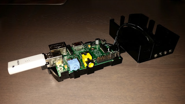
To make it able to send and receive with our home built remote control, we have to connect two circuits to our Raspberry Pi, one send circuit and one receive circuit.
The send circuit consists of a few parts while the receiver circuit (the ir receiver) can be soldered directly onto the raspberry.
The send circuit:
Since there are not too many components in the send circuit, no separate print plate is necessary to solder the components on.
I took my Raspberry Pi housing, drilled 4 holes in it to fit my IR leds, glued these to the casing with epoxy, soldered a resistor on each led’s anode, then lead two wires to my Raspberry Pi board where the leds cathode wire was soldered to the emitter of my transistor and the anode wire directly to pin 2 on the Raspberry Pi board (+5v).
I had soldered the collector of my transistor directly to pin 9 (GND) and the Base of my transistor to pin 11 (GPIO17)
The receive circuit:
The IR receiver can be soldered directly onto the Raspberry Pi’s pins 4 (+5v) – 5 (GND) – and 12 (GPIO18) respectively.
Configuring the Software.
The Raspberry Pi operating system.
Take the latest Raspbian version, as of writing, this is Raspbian Jessie from November 2015, download it from the Raspberry foundation website, put it to SD card and start off.
The Infrared software driver.
The linux platform (Raspbian in this case) already has packaged support for lirc – infrared control software for linux.
To interface this software with the hardware on the Raspberry Pi, a driver was written called lirc_rpi.
This driver is provided as an overlay kernel snapshot file which needs to be enabled in the configuration of the Raspberry Pi. Once enabled it loads when the Raspberry Pi boots up, no further loading via modules or modprobe is necessary.
To enable the lirc_rpi driver, we need to make a modification in the /boot/config.txt file
In the config file there is an option called: #dtoverlay=lirc-rpi
It needs to be uncommented and a small addition needs to be made to invert the IO logic to make this work properly. The config file resides on the /boot folder and is mapped on a read only partition, so we first need to remount it read/write to edit the config file.
Reboot your Raspberry Pi, it will load the lirc-rpi driver on boot now.
$ sudo reboot
The infrared control software.
As stated previously, the linux platform (Raspbian in this case) already has packaged support for lirc – infrared control software for linux, setting this up in Raspbian is just installing a package.
$ sudo apt-get -y install lirc
This will set up the required binaries and services for our remote control.
For a detailed description and manuals about this software, you can visit the lirc project website http://www.lirc.org/
configure your lirc hardware config file to reflect below configuration:
$ sudo vi /etc/lirc/hardware.conf
# Arguments which will be used when launching lircd
LIRCD_ARGS="--uinput"

# Don't start lircmd even if there seems to be a good config file
# START_LIRCMD=false

# Don't start irexec, even if a good config file seems to exist.
# START_IREXEC=false

# Try to load appropriate kernel modules
LOAD_MODULES=true

# Run "lircd --driver=help" for a list of supported drivers.
DRIVER="DEFAULT"

# usually /dev/lirc0 is the correct setting for systems using udev
DEVICE="/dev/lirc0"
MODULES="lirc_rpi"

# Default configuration files for your hardware if any
LIRCD_CONF=""
LIRCMD_CONF=""
The binaries that we will be using for our remote control are:
mode2 -> it can visualise ir reception on our ir sensor
irrecord -> this binary can sample keys from existing remote controls and record them to a config file
irsend -> send out ir control signal
Once the software is installed, a daemon called lircd will be running, it reads it’s configuration from /etc/lirc/lircd.conf – this file contains our remote control defenitions that we can send out amongst some other stuff.
To work manually with the above mentioned binaries we first need to stop the lircd daemon because it will interfere with our work otherwise:
$ sudo service lircd stop
To make sure our ir receiver is working properly, we will perform a small test, enter below command and point a remote control to your ir sensor and press a button, it should display remote control codes:
$ sudo mode2 -d /dev/lirc0
Once verified that our ir sensor is working, we can now start recording existing remote control buttons, launch below command and follow instructions, it will record a configuration file which we can feed to our ir daemon afterwards.
$ sudo irrecord -d /dev/lirc0 ~/lircd.conf
Once recorded, copy your remote control file to /etc/lirc/lircd.conf and start your lircd service:
$ sudo service lircd start
Once that the daemon is running with the recorded remote control configuration, you should be able to send out IR remote control codes, U can do a test by using below example.
Now that we have configured the Infrared hardware and software, it’s time to make it a bit more user friendly by installing a website for all this so we can easily use the remote control from any device which has a web browser.
There is a nice project on Github written by Alex Bain which just does all this:
For people wondering if the Raspberry Pi is a device on which you can safely implement OpenSSL on, please read my previous article about testing the True Random Number Generator on the Pi.
Why am I selecting a Raspberry Pi to host my Certificate Authority on one might ask?
Because it’s safe, small, cheap, fit’s on my SD card which can be put away on a safe place if not used… (want to do a double tier setup with it), and it’s cheaper than buying a certificate from an official provider.
I did more or less the same setup on Windows 2012R2, this worked very good, but it seems to have more overhead to set it up than a on a Rapberry Pi.
For people who are not really up to dat with what a Certificate Authority is, it’s better to first read up on some readily available resource before diving into this tutorial as to get a better understanding how this whole puzzle fit’s together. A suggestion for a nice article on X.509 certificates: https://en.wikipedia.org/wiki/X.509
So in this tutorial we will be building a Root Certificate authority on our Raspberry Pi with the OpenSSL toolkit.
First start off by downloading your copy of Raspbian Jessie Lite from the Raspberry Foundation web site, write to SD card, boot it up, and log in with username pi and raspberry as password.
Let’s get our Raspbian OS up to date:
expand your SD card with raspi-config
sudo apt-get update
sudo apt-get -y dist-upgrade
sudo apt-get install -y rpi-update
sudo rpi-update
The Raspbian Jessie Lite image from the raspberry pi foundation already seems to contain an installed version of openssl, the modify date of my Raspbian Jessie Lite image is 18/03/2016 and the installed openssl version is OpenSSL 1.0.1k 8 Jan 2015.
According to the openssl website this version will only be supported up to end of 2016.
For people wanting to compile a more recent version of OpenSSL, better first check out the release strategy of OpenSSL and verify what suit’s you best.
In our tutorial, we will be compiling a FIPS 140-2 compliant module for OpenSSL, a module compliant to the Federal Information Processing Standard of America, in other words, verified source code.
Now compare the resulting ‘digest ‘ with the ‘digest’ written down in the security policy, this needs to be an exact match, or else your download has been tampered with.
Unzip, configure, build, and install the module.
gunzip -c openssl-fips-2.0.12.tar.gz | tar xf -
cd openssl-fips-2.0.12
./config
make
sudo make install
Ok, we now have OpenSSL and a FIPS 140-2 compliant module in place for usage.
In your home folder, (/home/pi in my case) create a folder which will hold all the files for your Certificate Authority.
mkdir /home/pi/My-RootCA
cd /home/pi/My-RootCA
mkdir certs crl newcerts private
chmod 700 private
touch index.txt
echo 1000 > serial
Before we will start creating our certificate authority, we will build a configuration file with configuration details of our certificate authority. It will contain details needed by OpenSSL to perform it’s function. Save this file to your folder containing your certificate authority.
# OpenSSL Root Certificate Authority Configuration File.

[ openssl_conf_section ]
# Configuration module list
alg_section = evp_sect

[ evp_sect ]
# Set to “yes” to enter FIPS mode if supported
fips_mode = yes

[ ca ]
default_ca = CA_default

[ CA_default ]
# Directory and file locations.
dir               = /home/pi/My-RootCA
certs             = $dir/certs
crl_dir           = $dir/crl
new_certs_dir     = $dir/newcerts
database          = $dir/index.txt
serial            = $dir/serial
RANDFILE          = $dir/private/.rand

# The root key and root certificate.
private_key = $dir/private/My-RootCA.key.pem
certificate = $dir/certs/My-RootCA.cert.pem

# For certificate revocation lists.
crlnumber         = $dir/crlnumber
crl               = $dir/crl/My-RootCA.crl.pem
crl_extensions    = crl_ext
default_crl_days  = 90

# SHA-1 is deprecated, so use SHA-2 instead.
default_md        = sha512
name_opt          = ca_default
cert_opt          = ca_default
default_days      = 1825
preserve          = no
policy            = policy_strict

[ policy_strict ]
# The root CA should only sign intermediate certificates that match.
# See the POLICY FORMAT section of `man ca`.
countryName             = match
stateOrProvinceName     = match
organizationName        = match
organizationalUnitName  = optional
commonName              = supplied
emailAddress            = supplied

[ policy_loose ]
# Allow the intermediate CA to sign a more diverse range of certificates.
# See the POLICY FORMAT section of the `ca` man page.
countryName             = optional
stateOrProvinceName     = optional
localityName            = optional
organizationName        = optional
organizationalUnitName  = optional
commonName              = supplied
emailAddress            = optional

[ req ]
# Options for the `req` tool (`man req`).
default_bits        = 4096
distinguished_name  = req_distinguished_name
string_mask         = utf8only

# SHA-1 is deprecated, so use SHA-2 instead.
default_md          = sha512

# Extension to add when the -x509 option is used.
x509_extensions     = v3_ca

[ req_distinguished_name ]
countryName                     = Country Name (2 letter code)
stateOrProvinceName             = State or Province Name
localityName                    = Locality Name
0.organizationName              = Organization Name
organizationalUnitName          = Organizational Unit Name
commonName                      = Common Name
emailAddress                    = Email Address

# Optionally, specify some defaults.
countryName_default             = BE
stateOrProvinceName_default     = MyState
localityName_default            = MyCity
0.organizationName_default      = Private Individual
organizationalUnitName_default  = Crypto Security
emailAddress_default            = MyEmail@gmail.com

[ v3_ca ]
# Extensions for a typical CA (`man x509v3_config`).
subjectKeyIdentifier = hash
authorityKeyIdentifier = keyid:always,issuer
basicConstraints = critical, CA:true
keyUsage = critical, digitalSignature, cRLSign, keyCertSign
authorityInfoAccess = caIssuers;URI:http://My.Server.net:8080/pki/My-RootCA.cert.pem
crlDistributionPoints = URI:http://My.Server.net:8080:8080/pki/My-RootCA.crl.pem

[ v3_intermediate_ca ]
# Extensions for a typical intermediate CA (`man x509v3_config`).
subjectKeyIdentifier = hash
authorityKeyIdentifier = keyid:always,issuer
basicConstraints = critical, CA:true, pathlen:0
keyUsage = critical, digitalSignature, cRLSign, keyCertSign
authorityInfoAccess = caIssuers;URI:http://My.Server.net:8080/pki/My-IntermediateCA.cert.pem
crlDistributionPoints = URI:http://My.Server.net:8080/pki/My-IntermediateCA.cert.pem

[ usr_cert ]
# Extensions for client certificates (`man x509v3_config`).
basicConstraints = CA:FALSE
nsCertType = client, email
nsComment = “OpenSSL Generated Client Certificate”
subjectKeyIdentifier = hash
authorityKeyIdentifier = keyid,issuer
keyUsage = critical, nonRepudiation, digitalSignature, keyEncipherment
extendedKeyUsage = clientAuth, emailProtection

[ server_cert ]
# Extensions for server certificates (`man x509v3_config`).
basicConstraints = CA:FALSE
nsCertType = server
nsComment = “OpenSSL Generated Server Certificate”
subjectKeyIdentifier = hash
authorityKeyIdentifier = keyid,issuer:always
keyUsage = critical, digitalSignature, keyEncipherment
extendedKeyUsage = serverAuth

[ crl_ext ]
# Extension for CRLs (`man x509v3_config`).
authorityKeyIdentifier=keyid:always

[ ocsp ]
# Extension for OCSP signing certificates (`man ocsp`).
basicConstraints = CA:FALSE
subjectKeyIdentifier = hash
authorityKeyIdentifier = keyid,issuer
keyUsage = critical, digitalSignature
extendedKeyUsage = critical, OCSPSigning
We will now start to build our Root Certificate Authority.
First will generate an RSA key with random seed data taken from /dev/hwrng (our Raspberry Pi random number generator).
This key will be encrypted with the AES256 cipher and a seed password that we set for it.
Each time that we want to use this private key, we will need to provide the password to decrypt the private key.
Before commencing, you should remove and disable any network connectivity to your Raspberry Pi, remove any connected network cables, make sure you don’t have keyloggers and stuff, this for obvious reasons.
Before we will start creating our certificate authority, we will build a configuration file with configuration details of our certificate authority. It will contain details needed by OpenSSL to perform it’s function. Save this file to your folder containing your certificate authority.
# OpenSSL Intermediate Certificate Authority Configuration File.

[ openssl_conf_section ]
# Configuration module list
alg_section = evp_sect

[ evp_sect ]
# Set to “yes” to enter FIPS mode if supported
fips_mode = yes

[ ca ]
default_ca = CA_default

[ CA_default ]
# Directory and file locations.
dir               = /home/pi/My-IntermediateCA
certs             = $dir/certs
crl_dir           = $dir/crl
new_certs_dir     = $dir/newcerts
database          = $dir/index.txt
serial            = $dir/serial
RANDFILE          = /dev/hwrng

# The root key and root certificate.
private_key = $dir/private/My-IntermediateCA.key.pem
certificate = $dir/certs/My-IntermediateCA.cert.pem

# For certificate revocation lists.
crlnumber         = $dir/crlnumber
crl               = $dir/crl/My-IntermediateCA.crl.pem
crl_extensions    = crl_ext
default_crl_days  = 90

# SHA-1 is deprecated, so use SHA-2 instead.
default_md        = sha512
name_opt          = ca_default
cert_opt          = ca_default
default_days      = 1825
preserve          = no
policy            = policy_loose

[ policy_strict ]
# The root CA should only sign intermediate certificates that match.
# See the POLICY FORMAT section of `man ca`.
countryName             = match
stateOrProvinceName     = match
organizationName        = match
organizationalUnitName  = optional
commonName              = supplied
emailAddress            = supplied

[ policy_loose ]
# Allow the intermediate CA to sign a more diverse range of certificates.
# See the POLICY FORMAT section of the `ca` man page.
countryName             = optional
stateOrProvinceName     = optional
localityName            = optional
organizationName        = optional
organizationalUnitName  = optional
commonName              = optional
emailAddress            = optional

[ req ]
# Options for the `req` tool (`man req`).
default_bits        = 4096
distinguished_name  = req_distinguished_name
string_mask         = utf8only
# SHA-1 is deprecated, so use SHA-2 instead.
default_md          = sha512
# Extension to add when the -x509 option is used.
x509_extensions     = v3_ca

[ req_distinguished_name ]
countryName                     = Country Name (2 letter code)
stateOrProvinceName             = State or Province Name
localityName                    = Locality Name
0.organizationName              = Organization Name
organizationalUnitName          = Organizational Unit Name
commonName                      = Common Name
emailAddress                    = Email Address

# Optionally, specify some defaults.
countryName_default             = BE
stateOrProvinceName_default     = MyState
localityName_default            = MyCity
0.organizationName_default      = Private Individual
organizationalUnitName_default  = Crypto Security
emailAddress_default            = MyEmail@gmail.com

[ v3_ca ]
# Extensions for a typical CA (`man x509v3_config`).
subjectKeyIdentifier = hash
authorityKeyIdentifier = keyid:always,issuer
basicConstraints = critical, CA:true
keyUsage = critical, digitalSignature, cRLSign, keyCertSign
authorityInfoAccess = caIssuers;URI:http://My.Server.net:8080/pki/My-RootCA.cert.pem
crlDistributionPoints = URI:http://My.Server.net:8080/pki/My-RootCA.crl.pem

[ v3_intermediate_ca ]
# Extensions for a typical intermediate CA (`man x509v3_config`).
subjectKeyIdentifier = hash
authorityKeyIdentifier = keyid:always,issuer
basicConstraints = critical, CA:true, pathlen:0
keyUsage = critical, digitalSignature, cRLSign, keyCertSign
authorityInfoAccess = caIssuers;URI:http://My.Server.net:8080/pki/My-IntermediateCA.cert.pem
crlDistributionPoints = URI:http://My.Server.net:8080/pki/My-IntermediateCA.crl.pem

[ usr_cert ]
# Extensions for client certificates (`man x509v3_config`).
basicConstraints = CA:FALSE
nsCertType = client, email
nsComment = “OpenSSL Generated Client Certificate”
subjectKeyIdentifier = hash
authorityKeyIdentifier = keyid,issuer
keyUsage = critical, nonRepudiation, digitalSignature, keyEncipherment
extendedKeyUsage = clientAuth, emailProtection

[ server_cert ]
# Extensions for server certificates (`man x509v3_config`).
basicConstraints = CA:FALSE
nsCertType = server
nsComment = “OpenSSL Generated Server Certificate”
subjectKeyIdentifier = hash
authorityKeyIdentifier = keyid,issuer:always
keyUsage = critical, digitalSignature, keyEncipherment
extendedKeyUsage = serverAuth

[ crl_ext ]
# Extension for CRLs (`man x509v3_config`).
authorityKeyIdentifier=keyid:always

[ ocsp ]
# Extension for OCSP signing certificates (`man ocsp`).
basicConstraints = CA:FALSE
subjectKeyIdentifier = hash
authorityKeyIdentifier = keyid,issuer
keyUsage = critical, digitalSignature
extendedKeyUsage = critical, OCSPSigning
We will also be needing a private key for our Intermediate Certificate Authority, so we will generate one in the next step:
To also create a certificate for our Intermediate Authority, we will need to make a certificate signing request which we will sign with our root authority, since this is offline, we will need to copy this to usb drive and copy it over to our root authority.
For other parties to be able to verify the validity of our certificates by checking revocation information, we will generate a Certificate Revocation List on our Root Certificate Authority.
openssl ca -config intermediate/openssl.cnf \ -gencrl -out intermediate/crl/intermediate.crl.pem
Next you should copy the Root Certificate, Intermediate Certificate, and Certificate Revocation List to the “authorityInfoAccess” and “crlDistributionPoints” locations specified in your config files, so other parties would be able to trust or validate this information.
Now that we have authorized an Intermediate Certificate Authority in our certificate chain, there is no more immediate need for our Root Authority to stay online.
It should be taken offline and stored in a physically secured location. (like that coffee can buried in your backyard.)
The Intermediate Certificate Authority in the chain can now be used to sign any user or server certifcates.
If the integrity of your Intermediate Certificate Authority is breached, it will not damage the integrity of the Root Certificate Authority.
If you love the NSA like I do and want to understand how they succeed in invading our privacy by breaking our encrypted communication, you need to digest a lot of theoretical resources about cryptography.
A lot of security protocols exist nowadays, SSLv3/TLSv1.2 and SSHv2 beïng the more known and used protocols.
Knowing the weaknesses of these protocols, and therefore beïng able to correctly implement these protocols in your networking infrastructure seems trivial nowadays if you want to avoid any man-in-the-middle listening in.
It seems evidently that an important factor for good security is the entropy of your random number data used to generate your secrets with.
Entropy is a measure for randomness, and provides a way to express the ‘quality of randomness’ of your starting number data for your secret.
If an attacker were to be able to predict the randomness of these numbers, he would subsequently be able to perform effective brute force techniques against the encrypted data, eventually revealing the contents of the encrypted data.
In our tutorial for today we will be visualising and testing random number data used as starting point for our cryptographical systems.
The Raspberry Pi has a TRNG (True Random Number Generator) built into it’s SOC.
We will check if the data produced by this TRNG is able to withstand a FIPS 140-2 test.
FIPS is the American Information Processing Standard.
First start off by downloading your copy of Raspbian Jesslie Lite from the Raspberry Foundation web site, write to SD card, boot it up, and log in with username pi and raspberry as password.
The release date of the Raspbian Jessie lite image used for this tutorial was 18/03/2016.
Note that for this installation a Raspberry Pi model B was used.
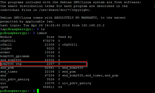
To enable the True Random Number Generator on the Raspberry Pi a kernel module needs to be loaded:
bcm2708_rng or bcm2835_rng
The first one is from an older revision kernel, which is now obsolete I believe.
When performing an lsmod on the Raspbian Jessie Lite image we can see that the kernel module for the True Random Number Generator is already loaded.
You can also verify it’s presence by checking if the /dev/hwrng entry exists.
If you notice that you don’t have this device available on your device, you can always load the kernel modules for it, either manually or at boot time.
modprobe bcm2835_rng  # will load the kernel module on request
echo bcm2835_rng | sudo tee -a /etc/modules  # add it to our modules file to load at boot-time
You can check it’s output by dumping a few raw blocks of it to stdout.
sudo dd bs=1024 count=2 if=/dev/hwrng of=-
A few blocks of random binary data should now be displayed.
Random data, when visualised, looks like static, or so-called snow, which you could see on an old television so many years ago. It’s truely random data visualised because of the absense of any predetermined signalling for visualisation.
On linux, we can visualise random data with the netpbm toolkit.
This toolkit can be installed with:
sudo apt-get install -y netpbm
Creating a visual image from the data can be accomplished by reading data bytes from the TRNG, converting these bytes into a portable pixmap, which is subsequently converted to a .png (image) file.
In below example, we read 1024 * 1024 = 1048576 bytes to convert it to an image
When viewing the image, we can see that it looks like static on our old television.
To test our random data for FIPS compliance we will need to install rng-tools:
sudo apt-get install rng-tools
rng-tools contains rngtest, a tool to test our random data against fips compliance.
It performs a series of statistical tests to determine if the entropy of our data matches up against FIPS regulations.
sudo cat /dev/hwrng | rngtest -c 1000
rngtest 2-unofficial-mt.14
Copyright (c) 2004 by Henrique de Moraes Holschuh
 This is free software; see the source for copying conditions.  There is NO warranty; not even for MERCHANTABILITY or FITNESS FOR A PARTICULAR PURPOSE.
 rngtest: starting FIPS tests…
 rngtest: bits received from input: 20000032
 rngtest: FIPS 140-2 successes: 998
 rngtest: FIPS 140-2 failures: 2
 rngtest: FIPS 140-2(2001-10-10) Monobit: 0
 rngtest: FIPS 140-2(2001-10-10) Poker: 0
 rngtest: FIPS 140-2(2001-10-10) Runs: 1
 rngtest: FIPS 140-2(2001-10-10) Long run: 1
 rngtest: FIPS 140-2(2001-10-10) Continuous run: 0
 rngtest: input channel speed: (min=17.254; avg=906.875; max=1502403.846)Kibits/s
 rngtest: FIPS tests speed: (min=839.909; avg=4210.622; max=6403.689)Kibits/s
 rngtest: Program run time: 27489439 microseconds
A few failures seems normal on these statistical tests, in our example case 0,2% of failures are noted against our data.
It gives you a fair idea how safe the entropy of your data is for usage in cryptographical systems.
Windows XP and Windows Server 2003 certificate clients do not support the Alternate Signature Algorithm. If you want these clients to be able to enroll for certificates, do not add the line AlternateSignatureAlgorithm=1 to the CAPolicy.inf.
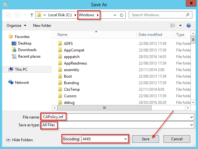
Save the file as C:\Windows\CAPolicy.inf, make sure to save it in the ANSI encoding format.
To install the Enterprise Subordinate CA Role:
1. In Server Manager, click Manage, and then click Add Roles and Features.
2. On the Before you begin screen, click Next.
3. On the Select installation type screen, ensure the default selection of Role-based or feature-based installation is selected. Click Next.
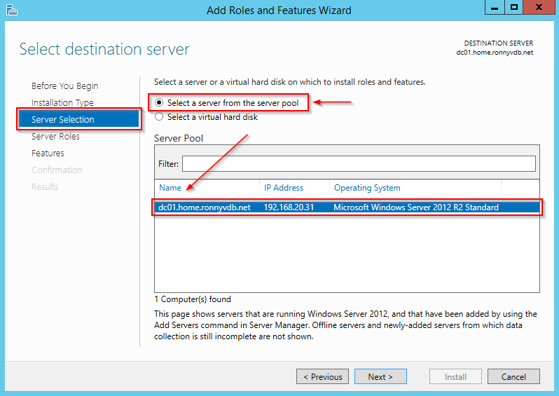
4. On the Select destination server screen, ensure that DC01 is selected and then click Next.
5. On the Select server roles screen, select the Active Directory Certificate Services role.
6. When prompted to install Remote Server Administration Tools click Add Features. Click Next.
7. On the Select features screen, click Next.
8. On the Active Directory Certificate Services screen, click Next.
9. On the Select role services screen, the Certification Authority role is selected by default. Click Next.
10. On the Confirm installation selections screen, verify the information and then click Install.
11. Wait for the installation to complete. The installation progress screen is displayed while the binary files for the CA are installed.
The necessary files have now been installed for our Certificate Services Role.
Configuring Active Directory Certificates Services on the destination server.
1. When the binary file installation is complete, click the Configure Active Directory Certificate Services on the destination server link.
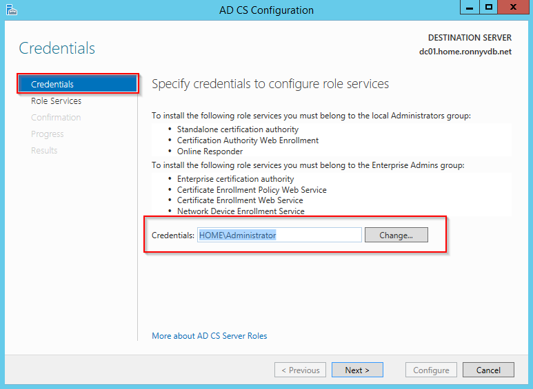
2 On the Credentials screen, you should see that the DOMAIN\Administrator is displayed in the Credentialsbox. Click Next.
3. On the Role Services screen, select Certification Authority. This is the only available selection when only the binary files for the certification authority role are installed on the server. Click Next.
4. On the Setup Type screen, ensure that Enterprise CA is selected and then click Next.
5. On the CA Type screen, select Subordinate CA to install an Enterprise Subordinate CA. Click Next.
6. On the Private Key screen, leave the default selection to Create a new private key selected. Click Next.
7. On the Cryptography for CA screen, ensure that the cryptographic provider is RSA#Microsoft Software Key Storage Provider, the key length is set to 2048 and the hash algorithm is set to SHA1 then click Next.
Do not select the Allow administrator interaction when the private key is accessed by the CAcheckbox. This setting is typically used with Hardware Security Modules (HSMs) and similar key protection devices prompt for additional information when the private key is accessed.
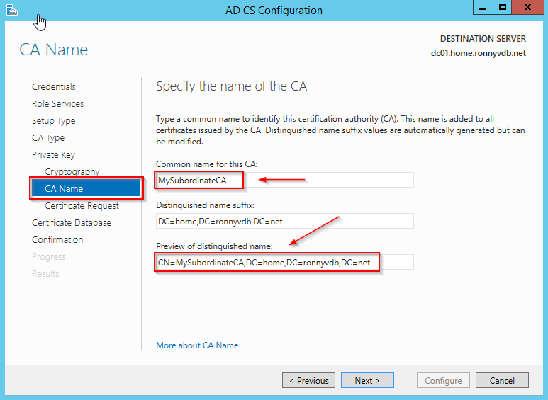
8. On the CA Name screen, in the Common name for this CA text box, type MySubordinateCA and then clickNext.
Note that your distinguished name should be automatically expanded to cover your domain name as well.
9. On the Certificate Request screen, notice that Save a certificate request to file on the target machine is selected. This is the correct option because we are using an offline parent CA (the root CA) in this configuration. Leave the default and click Next.
10. On the CA Database screen, leave the default locations for the database and database log files. Click Next.
11. On the Confirmation screen, click Configure.
12. On the Results screen, you see that you must take the certificate request to the RootCA in order to complete the configuration. Click Close
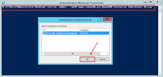
13. Once that you have your certificate request file copied onto your Root Certificate Authority, submit it to your CA.
14. On ROOTCA, you must approve the request. You can do this using Server Manager or by using certutil from the command line.
In Server Manager, click Tools and then click Certification Authority.
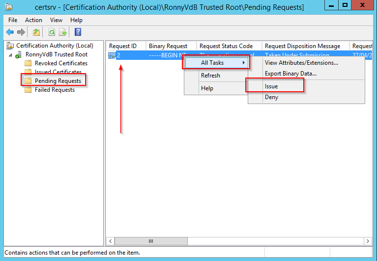
To use Server Manager, click Tools, and then click Certification Authority. Expand the RootCA object and then click Pending Requests.
Right-click the Request ID that corresponds with the one you saw when you submitted the request in the previous step. Click All Tasks and then click Issue.
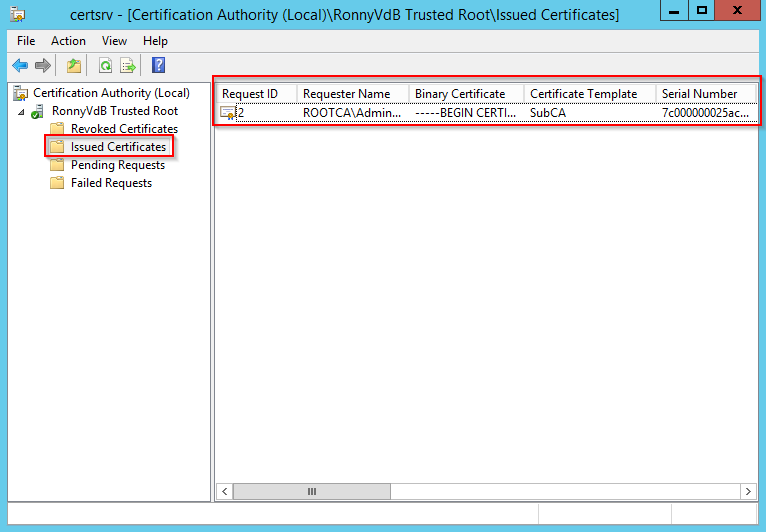
Click Issued Certificates and see the issued certificate in the Details pane.
From the command prompt on ROOTCA, retrieve the issued certificate by running the command
At this point you can shut down your ROOTCA, and protect it from access by anyone, until you need to regenerate your Enterprise Subordinate CA (in 10 years);
Configuring Certificate Revocation Lists and Authority Information Access
In a powershell session, we will configure the the CDP and AIA settings for our Enterprise Subordinate CA.
Open a powershell window and enter the following commands:
To enable computer certificate auto enrollment, you will need to run through 2 procedures:
Enable certificate autoenrollment through Group Policy
Configure a client and server authentication certificate template for autoenrollment
To enable certificate autoenrollment through Group Policy
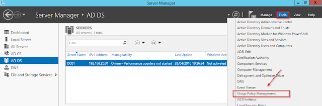
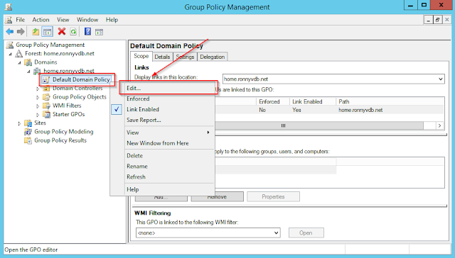
On DC1, sign in as Administrator. In Server Manager, click Tools, and then click Group Policy Management.
In your group policy management console, edit your default domain policy
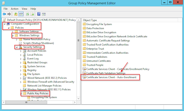
In your default domain policy, go over to Computer Configuration – Policies – Windows Settings – Security Settings – Public Key Policies – and open – Certificate Services Client – Certificate Enrollment Policy
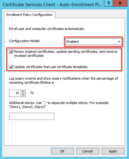
Select Renew expired certificates, update pending certificates, and remove revoked certificates andUpdate certificates that use certificate templates. Click OK.
The auto enrollment will not work unless we configure a client server authentication certificate template for autoenrollment
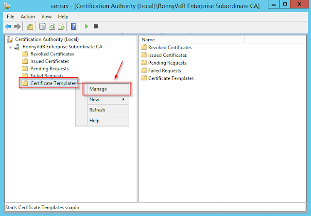
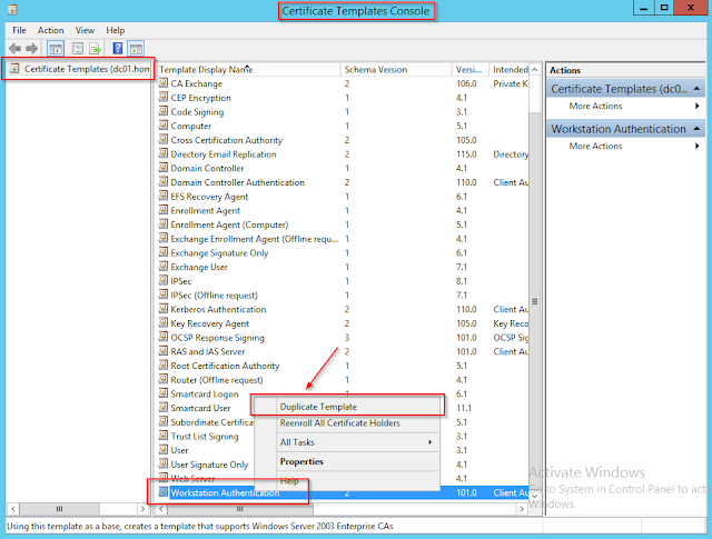
On DC01, in the Certification Authority console pane, right click Certificate Templates and select Manage.
In the details pane, right-click Workstation Authentication and then click Duplicate Template.
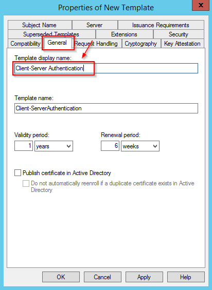
Click the General tab, in Template display name, type Client-Server Authentication.
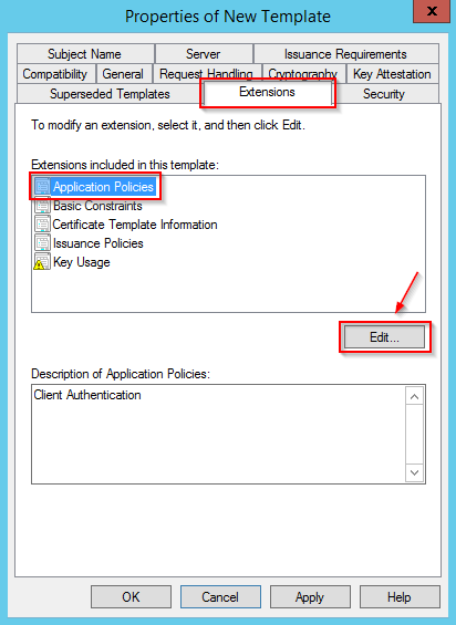
Click the Extensions tab, ensure Application Policies is selected, and then click Edit.
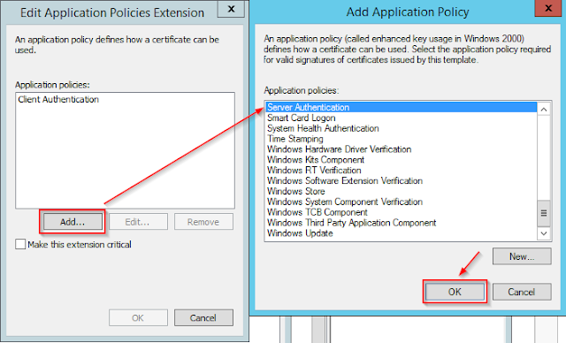
Click Add then click Server Authentication. Click OK twice.
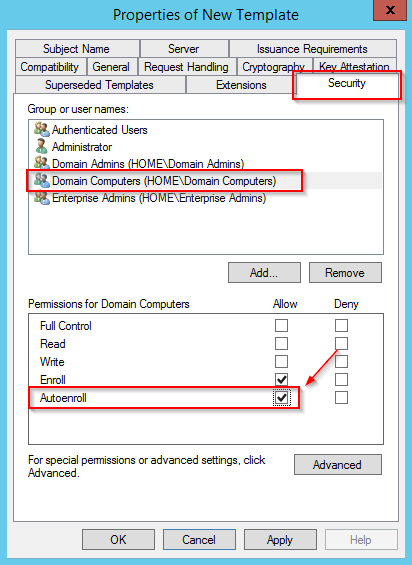
On the Properties of New Template dialog, click the Security tab.
In Group or user names, click Domain Computers (CORP\Domain Computers).
In the Autoenroll row, select the Allow checkbox. This will cause all domain computers to automatically enroll for certificates using this template. Now click ok to close the properties of the new template.
Note:
You would typically not assign a template both the Client Authentication and the Server Authentication enhanced key usage (EKU). Also, Server Authentication EKU are typically not configured for autoenrollment. This is done in this lab only for convenience and compatibility with other labs.
Note:
The computers also need Read permission for the template in order to enroll. However, this permission is already granted to the Authenticated Users group. All computer accounts in the domain are members of Authenticated Users, so they already have the permission to Read the template.
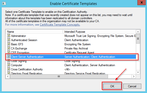
Before this template will do it’s work, you need to issue it.
Right-click Certificate Templates, click New, click Certificate Template to Issue.
In the Enable Certificate Templates dialog box, click Client-Server Authentication and then click OK. Close the Certification Authority console.
This lab guide is a consolidated description on how to set up a two tier PKI infrastructure on Windows 2012 R2 with Active Directory Certificate services.
This guide contains instructions for installing a standalone offline root CA, and an enterprise issuing CA (two-tier PKI hierarchy).
In this guide you will deploy a two-tier PKI hierarchy, configure a certificate revocation list (CRL) distribution point (CDP), automatically deploy certificates to the domain, and utilize a certificate.
This lab tutorial requires that you have 2 servers, installed with Windows 2012 R2.
ROOTCA:
A Windows 2012 R2 Stand Alone server, not domain-joined. This server will be used to deploy our offline Root CA.
DC01:
A Windows 2012 R2 Server, promoted to domain controller in a new forest.
Installing the standalone offline root CA:
To complete this installation we will be performing below steps:
Prepare the CAPolicy.inf for the standalone root CA
Install the standalone root CA
Configure the Root CA Authority Information Access and Certificate Distribution Point settings
Copy the root CA certificate and CRL to removable media
Distribute the root CA via GPO
Create an internal contoso.com DNS zone and www host record
To prepare the CAPolicy.inf for the standalone root CA
Open Windows PowerShell
Type: notepad c:\Windows\CAPolicy.inf and press ENTER.
When prompted to create a new file, click Yes.Enter the following as the contents of the file:
Windows XP and Windows Server 2003 certificate clients do not support the Alternate Signature Algorithm. If you want these clients to be able to enroll for certificates, do not add the line AlternateSignatureAlgorithm=1 to the CAPolicy.inf.
Note:
In the above example there is an OID (object identifier) noted from Microsoft. Individual organizations should obtain their own OIDs. The preferred way to obtain a root object identifier (OID) is to request one from an International Standards Organization (ISO) Name Registration Authority. This is a one-time action; when you have obtained a root OID, the OID space it defines is yours and you can administer it yourself. For this tutorial, we will be using Microsoft’s OID.
Note:
Setting the CRLDeltaPeriodUnits=0 in the CAPolicy.inf disables Delta CRL publishing, which is the appropriate setting for an offline Root CA.
Save the file as C:\Windows\CAPolicy.inf, make sure to save it in the ANSI encoding format.
To install the standalone Root CA Role:
1. In Server Manager, click Manage, and then click Add Roles and Features.
2. On the Before you begin screen, click Next.
3. On the Select installation type screen, ensure the default selection of Role-based or feature-based installation is selected. Click Next.
4. On the Select destination server screen, ensure that ROOTCA is selected and then click Next.
5. On the Select server roles screen, select the Active Directory Certificate Services role.
6. When prompted to install Remote Server Administration Tools click Add Features. Click Next.
7. On the Select features screen, click Next.
8. On the Active Directory Certificate Services screen, click Next.
9. On the Select role services screen, the Certification Authority role is selected by default. Click Next.
10. On the Confirm installation selections screen, verify the information and then click Install.
11. Wait for the installation to complete. The installation progress screen is displayed while the binary files for the CA are installed.
The necessary files have now been installed for our Certificate Services Role.
Configuring Active Directory Certificates Services on the destination server.
1. When the binary file installation is complete, click the Configure Active Directory Certificate Services on the destination server link.
2 On the Credentials screen, you should see that the ROOTCA\Administrator is displayed in the Credentialsbox. Click Next.
3. On the Role Services screen, select Certification Authority. This is the only available selection when only the binary files for the certification authority role are installed on the server. Click Next.
4. The only selection available on the Setup Type screen is Standalone CA. This is because the account used to install is a member of the local Administrators group and the server is not a member of an Active Directory Domain Services (AD DS) domain. Click Next.
5. In the CA Type screen, Root CA is selected by default. Click Next.
6. On the Private Key screen, leave the default selection to Create a new private key selected. Click Next.
7. On the Cryptography for CA screen, ensure that the cryptographic provider is RSA#Microsoft Software Key Storage Provider, the key length is set to 2048 and the hash algorithm is set to SHA1 then click Next.
Do not select the Allow administrator interaction when the private key is accessed by the CAcheckbox. This setting is typically used with Hardware Security Modules (HSMs) and similar key protection devices prompt for additional information when the private key is accessed.
8. On the CA Name screen, in the Common name for this CA text box, type MyRootCA and then clickNext.
9. On the Validity Period screen, enter 20 for the number of years for the certificate to be valid.
10. On the CA Database screen, leave the default locations for the database and database log files. Click Next.
11. On the Confirmation screen, click Configure.
12. The Progress screen is displayed during the configuration processing, then the Results screen appears. Click Close. If the Installation progress screen is still open, click Close on that screen as well.
Configuring Certificate Revocation Lists and Authority Information Access
In Server Manager, click Tools and then click Certification Authority.
In the Certification Authority console tree, expand MyRootCA. Right-click Revoked Certificates and then click Properties.
On the CRL Publishing Parameters tab, ensure that Publish Delta CRLs is cleared (not selected). Click OK.
In the Certification Authority console tree, right-click MyRootCA and then click Properties.
Click the Extensions tab. Ensure that Select extensions is set to CRL Distribution Point (CDP) and in theSpecify locations from which users can obtain a certificate revocation list (CRL), review the default settings.
Change Select extension to Authority Information Access (AIA) and review the default settings. Click OK. If you are prompted to restart Active Directory Certificate Services, click No. You will restart the service after modifying the default paths in the next step.
Now configure our AIA and CDP url’s and additional expiry information. This should be done in powershell.
Remove the current CAAuthorityInformationAccess locations
$aialist = Get-CAAuthorityInformationAccess; foreach ($aia in $aialist) {Remove-CAAuthorityInformationAccess $aia.uri -Force};
Restart certificate services to activate this configuration.
restart-service certsvc
Trigger a manual publish of a certificate revocation list
certutil -crl
Copy the root CA certificate and CRL to removable media (usb stick) and paste in the CDP and / or AIA location
From Windows PowerShell, run the command dir C:\Windows\system32\certsrv\certenroll\*.cr*, which displays the certificates and CRLs in the default certificate store.
Copy the CA certificate file and CRL to removable media. For example, if you were running commands to copy the certificate and CRL to a floppy disk drive (A:), you would run the following commands:
Now log in to your domain server that will become your subordinate certificate authority and insert your removable media
Publish the “ROOTCA_RonnyVdB Trusted Root.crt” certificate into the configuration container of AD, this will make all machines on the domain trust this certificate without need for group policy distribution.
Add the “ROOTCA_RonnyVdB Trusted Root.crt” certificate to the local certificate store, normally this happens at next group policy update, but this speeds up the process
If we want to modify partitions and file systems in our disk image file, we will need to mount the image as a so-called loop device in linux.
Not only will we need to mount the image as a loop device, but we also need to make sure that our loop device will auto create additional device entries for the partitions detected on our image.
On Ubuntu, this function is baked into the linux kernel, and this functionality can be enabled in the following way:
edit /etc/default/grub
Add the following:
max_loop=64
As last parameter on the following line:
GRUB_CMDLINE_LINUX_DEFAULT=""
Now execute to activate: , reboot and verify with
update-grub2
Now reboot your station and verify if the loop devices are available with:
ls /dev/loop*
for ubuntu 16.04 LTS
sudo losetup -Pf disk_image.raw
You can list the partition table of an image file with the following command:
fdisk -l my-raw-imagefile.img
We gather from the partition table that we have two available partitions in the image file.
Before we can make any modification to the partitions or filesystems in our image, we will first need to mount the image as a loop device, which will install the required dev entries to address our partitions with other software as gparted.
To mount the image as a loop device:
sudo losetup --find --show my-raw-imagefile.img
This will mount /dev/loop0 as a ‘virtual raw disk’ and it’s containing partitions accordingly as /dev/loop0p1 and /dev/loop0p2
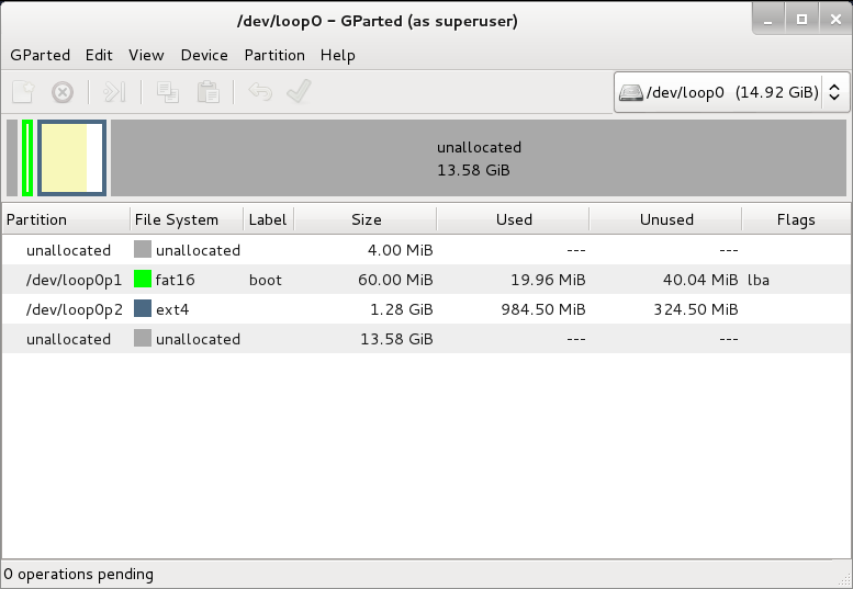
Now that we have set-up our raw imagefile as a loop device, we can run filesystem tools on it. We can use for example gparted to resize the file systems contained in the partitions of our image:
gparted /dev/loop0
Do any resize operation that you would like to have for your partitions and apply them, in my case I needed to trim down my image size as small as possible.
Now that the resize operations have been done in our raw disk image, we will dump the partitions to a smaller image.
First remove our loop device for the image, as it will interfere with the dump process:
sudo losetup -d /dev/loop0
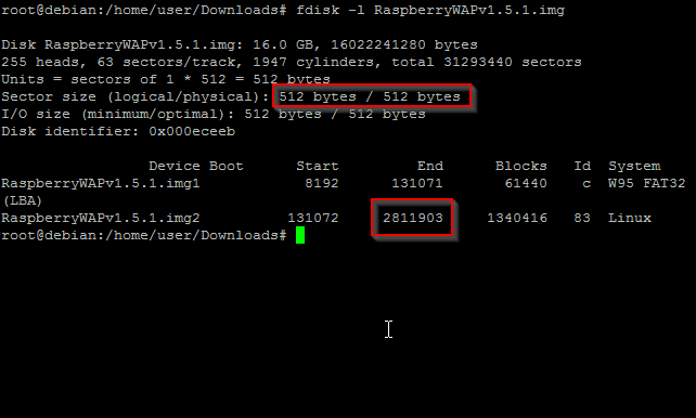
Now list our partition table so we have an idea what to dump:
In our partition table we can see that our blocks are 512 bytes long, and we have a total number of 2811903 blocks to dump … doing the actual dump is done with dd which just reads raw blocks of data and dumps them somwhere.
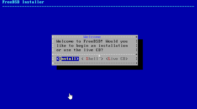
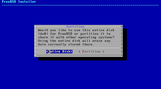
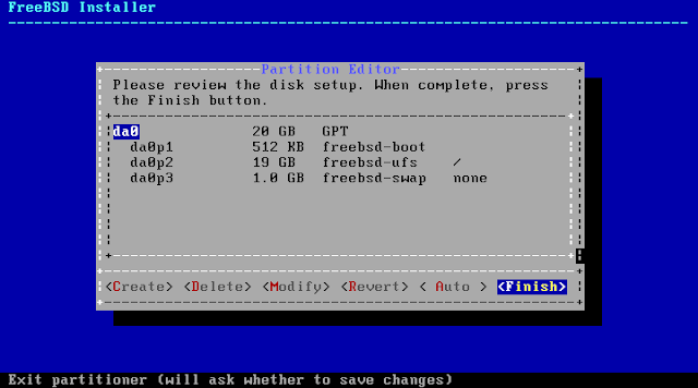
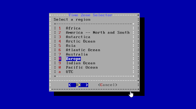
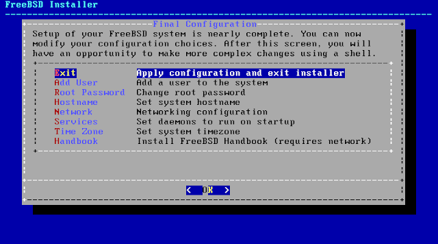
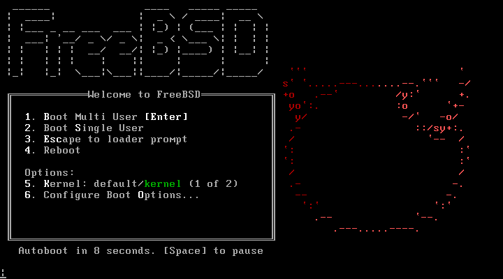
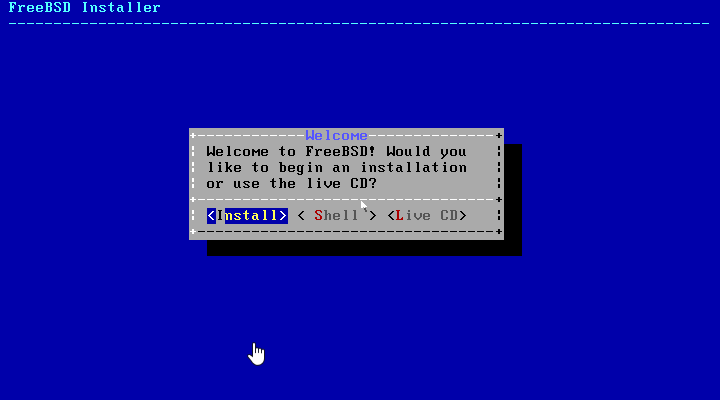
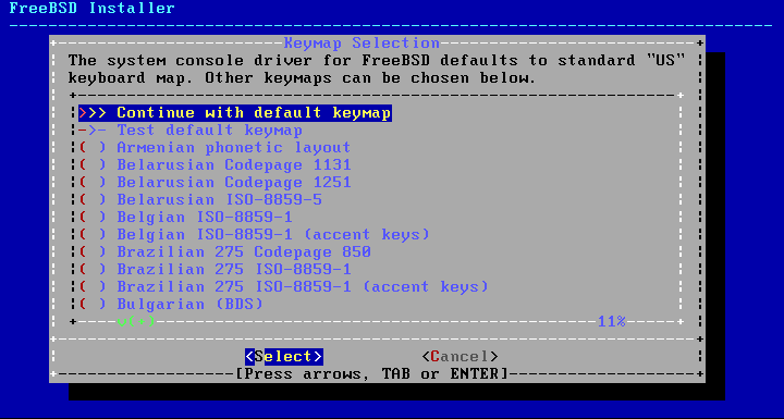
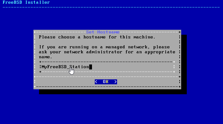
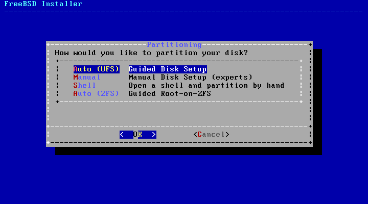
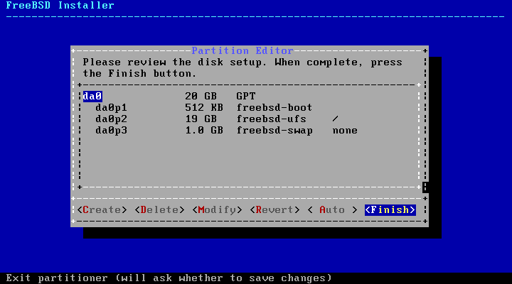
If you ever come across a scenario where you are in need of a FreeBSD machine to tinker a bit with, look no further but come and join me in my quick tutorial to set one up on the fly.
Before we can begin with this tutorial it’s assumed you already have Vmware workstation installed and the FreeBSD ISO installation file downloaded and ready.
For the sake of reference, here’s where you can download this software:
If you try to run the tools with ./vmware-install.pl, you’ll get an error “command not found”. That’s because the provided script is looking for perl under /usr/bin. As of FreeBSD 10.1, perl is no longer a system binary and after the install, the binary is under /usr/local/bin.
So, edit the following files and replace /usr/bin/perl with /usr/local/bin/perl in the following three files. It’s the first line in all three files.
vmware-install.pl
vmware-install.real.pl (if you have VMware Workstation 12)
bin/vmware-config-tools.pl
bin/vmware-uninstall-tools.pl
At the end of the vmware tools installaltion, you will be able to start the VMware Tools by invoking:
/usr/local/bin/vmware-toolbox-cmd
Your FreeBSD Virtual Machine Network:
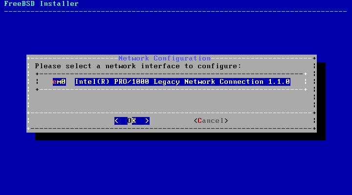
In default, your virtual machine will boot presenting an intel network driver to the FreeBSD OS which the OS recognises and has a driver for, and hence the OS will be able to use that network interface.
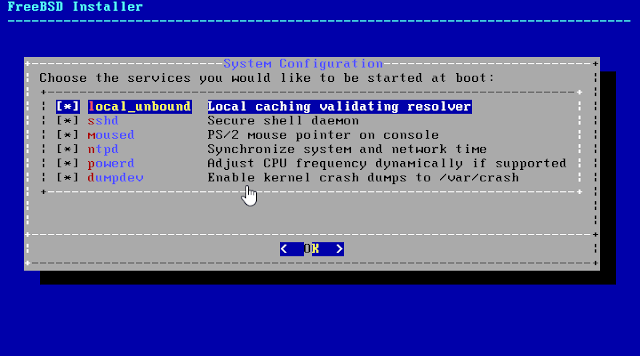
The install comments of the VMware tools note that u need to add the following line to /etc/rc.conf
ifconfig_vxn0=”DHCP”
You need to take this comment with a grain of salt. In default configuration the /etc/rc.conf file will specify a line which makes the machine use the default Intel network driver.
ifconfig_em0=”DHCP”
You should only change it to the line proposed if you want to make usage of the vmxnet driver in VMware Workstation, actually a few changes are required if you want to do this.
1. You will need to shudown your virtual machine, edit your vmx file and change the following line (this will switch the network driver for your virtual machine from Intel to vmxnet after rebooting):
ethernet0.virtualDev = “e1000” into ethernet0.virtualDev = “vmxnet”
2. In your /etc/rc.conf you will need to change to following line:
ifconfig_em0=”DHCP” into ifconfig_vxn0=”SYNCDHCP”
3. In your /usr/local/etc/rc.d/vmware-guestd you have to change the following line so that the VMware tools guest daemon would start before “netif”.
# BEFORE: LOGIN into # BEFORE: LOGIN netif
I leave it up to your judgement if you really need this change. A possible benefit I guess is that the vmxnet driver supports 10G nic’s.
In my case after making this change, dhcp wasn’t giving me any ip address, so I configured an IP address manually by inserting below into /etc/rc.conf


