For diagnostic purposes, it migt be sometimes necessary to perform a remote capture of network traffic on some linux box. It comes in handy that we can do this remotely from a laptop running windows and wireshark, this way we don’t need to, first create a packet capture file and transfer this to our computer. Instead, this procedure connects over ssh to the remote linux, starts tcpdump, redirects the output in realtime over the ssh connection to our windows machine and inputs this into wireshark.
The tools we are using for this on Windows is plink.exe (known from the putty suite of tools), tcpdump and Wireshark.
Before we start monitoring, we will need to give tcpdump permission to capture raw packets:
Capturing a sniffer dump on a linux machine is easy, we can install the tcpdump package to capture network packets and write these to a file for further analysis with wireshark.
apt-get install tcpdump
tcpdump -i <interface> -s 65535 -w <some-file>
You can transfer the file thereafter with WinSCP to your Windows station for analysis.
Sniffing on the linux machine with redirection to your Windows wireshark
If you have putty and plink installed, you can also capture directly on a remote linux machine and redirect this to your windows station’s wireshark for realtime analysis.
If you are using password authentication on the linux machine:
These steps are required once on your computer, not every time you connect. However, you’ll likely need to install newer versions of the software periodically.
Open an elevated Windows PowerShell command prompt (run Windows PowerShell as an administrator).
In the Administrator: Windows PowerShell command window, run this command:
Install-Module -Name AzureAD -AllowClobber
Step 2: Connect to your Office 365 subscription
To connect with just an account name and password :
$UserCredential = Get-Credential
Connect-AzureAD -Credential $UserCredential
To connect with multi-factor authentication (MFA) :
Fill in the values for the $adminUPN and $orgName variables (replacing all the text between the quotes, including the < and > characters), and then run the following commands at the SharePoint Online Management Shell command prompt:$adminUPN=”<the full email address of a SharePoint administrator account, example: jdoe@contosotoycompany.onmicrosoft.com>” $orgName=”<name of your Office 365 organization, example: contosotoycompany>” $userCredential = Get-Credential -UserName $adminUPN -Message “Type the password.” Connect-SPOService -Url https://$orgName-admin.sharepoint.com -Credential $userCredential
When prompted with the Windows PowerShell credential request dialog box, type the password for the SharePoint Online SharePoint administrator account.
To connect with multifactor authentication (MFA)
Fill in the value for the $orgName variable (replacing all the text between the quotes, including the < and > characters), and then run the following commands at the SharePoint Online Management Shell command prompt:$orgName=”<name of your Office 365 organization, example: contosotoycompany>” Connect-SPOService -Url https://$orgName-admin.sharepoint.com
When prompted with the Microsoft SharePoint Online Management Shell dialog box, type the account name and password for a SharePoint administrator account, and then click Sign in.
Follow the instructions in the Microsoft SharePoint Online Management Shell dialog box to provide the additional authentication information, such as a verification code, and then click Sign in.
You are now ready to begin executing SharePoint Online commands.
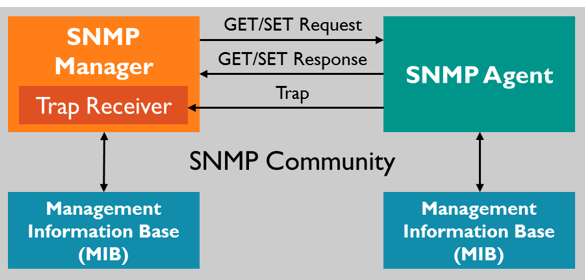
By default the snmpd daemon daemon listens only to connections from the local host, we need to change the agentAddress parameter so the SNMP daemon will listen on all IP addresses.
For Ubuntu 10.04.4 LTS:
vi /etc/default/snmpd
# remove 127.0.0.1 from snmpdopts
For other distributions:
# Listen for connections from the local system only
# agentAddress  udp:127.0.0.1:161 <-- put this entry in comment
# Listen for connections on all interfaces (both IPv4 and IPv6)
agentAddress udp:161,udp6:[::1]:161  <-- add this entry to make it listen to all IP addresses
Restart your daemon for the changes to take effect.
service snmpd restart
Create an authentication user for SNMPv3:
In our set-up we will be utilising SNMPv3 with an encrypted connection and user authentication. To facilitate in this we will need to create a SNMP user account and password to validate our connection to the SNMP server.
automated
service snmpd stop
net-snmp-config --create-snmpv3-user -ro -A password -X password -a MD5 -x AES snmpv3user

service snmpd start
or manually
service snmpd stop
echo 'createUser snmpv3user MD5 "password" AES' | sudo tee -a /var/lib/snmp/snmpd.conf

echo 'rouser snmpv3user' | sudo tee -a /usr/share/snmp/snmpd.conf
service snmpd start
Testing the SNMP daemon
Let’s test our snmp daemon with snmpwalk, if everything is ok, we should be able to walk the snmp tree.
snmpwalk -v3 -a MD5 -x AES localhost -u snmpv3user -A password
If it doesn’t work when trying this from another station, it might be possible that the iptables firewall is blocking the connection to your snmp daemon.
Apparently snmpd is not working by default on debian systems. On debian systems we need to install the snmp mibs, these do not come bundled with the snmpd package. We can download the mibs with a package called: snmp-mibs-downloader But before we can install this downloader, we need activate our non-free repositories for apt.
echo "deb http://ftp.us.debian.org/debian/ jessie main non-free" >> /etc/apt/sources.list
echo "deb-src http://ftp.us.debian.org/debian/ jessie main non-free" >> /etc/apt/sources.list
You have built two or more network cards into one Linux system and each of these cards has its own default gateway. By default, you can only have one default gateway on a system. The case described would lead to asynchronous routing, whereby the router would reject the packets as appropriate.
Solution
The iproute2 program, which is included in all current Linux distributions and already installed even, as a rule, can be used for the solution of this problem. Normally, a Linux system only has one routing table, in which only one default gateway can make entries. With iproute2, you have the ability to setup an additional routing table, for one thing, and allow this table to be used by the system based on rules, for another.
Initial Position
We will assume that we have two interfaces: eth0 and eth1. The two networks that should be used are 192.168.0.0/24 and 10.10.0.0/24, whereby the first IP address in each respective network should be the gateway. Under Debian, the initial configuration would appear as follows. /etc/network/interfaces
$ sudo vi /etc/network/interfaces
# This file describes the network interfaces available on your system
# and how to activate them. For more information, see interfaces(5).
# The loopback network interface auto lo iface lo inet loopback
# The primary network interface

allow-hotplug eth0 iface eth0 inet static
     address 192.168.0.10
     netmask 255.255.255.0
     gateway 192.168.0.1

# The secondary network interface allow-hotplug eth1 iface eth1 inet static
     address 10.10.0.10     netmask 255.255.255.0
Adding a Second Routing Table
To add a new routing table, the file, /etc/iproute2/rt_tables must be edited. We will call the routing table “rt2” and set its preference to 1.
$ sudo vi /etc/iproute2/rt_tables
#
# reserved values
#
255     local
254     main
253     default
0       unspec
#
# local
#
#1      inr.ruhep
rt2
Configuring the New Routing Table
From this point, four commands are needed to achieve our goal. First, the new routing table needs to be populated, which is done using the following command.
$ sudo ip route add 10.10.0.0/24 dev eth1 src 10.10.0.10 table rt2
$ sudo ip route add default via 10.10.0.1 dev eth1 table rt2
The first command says that the network, 10.10.0.0/24, can be reached through the eth1 interface. The second command sets the default gateway.
Routing Rules
So that the system knows when to use our new routing table, two rules must be configured.
$ ip rule add from 10.10.0.10/32 table rt2 ip rule add to 10.10.0.10/32 table rt2
These rules say that both traffic from the IP address, 10.10.0.10, as well as traffic directed to or through this IP address, should use the rt2 routing table.
Making the Configuration permanent
The ip rule and ip route commands will become invalid after a re-boot, for which reason they should become part of a script (for example, /etc/rc.local) that will be executed once the network has been started after booting. For Debian, these command can also be written directly into the /etc/network/interfaces file, which would then appear as follows.
$ sudo vi /etc/network/interfaces
iface eth1 inet static
	address 10.10.0.10
	netmask 255.255.255.0
	post-up ip route add 10.10.0.0/24 dev eth1 src 10.10.0.10 table rt2
	post-up ip route add default via 10.10.0.1 dev eth1 table rt2
	post-up ip rule add from 10.10.0.10/32 table rt2
	post-up ip rule add to 10.10.0.10/32 table rt2
More than Two Network Cards or Gateways
If there are more than two networks, a routing table can be created for each additional network analogous to the example presented above.
Testing the Configuration
The following commands can be used to ensure that the rules as well as the routing entries are working as expected.
$ sudo ip route list table rt2
$ sudo ip rule show
Configuring windows time in an active directory domain from zero to hero.
In a domain environment the master clock is hosted on the domain controller which holds the PDC emulator role. This domain controller synchronizes it’s time from an external time source
All other domain controllers and workstations utilize the domain hierarchy to locate their time source.
Resetting and restoring the entire domain time synchronisation hierarchy consists of the following steps:
1. Reset the windows time service on the domain controller that holds the PDC emulator and reconfigure the pdc emulator with an external time source.
2. Reset the time service on any domain member server and reconfigure them to follow the domain hierarchy
3. If necessary, reset any workstations and reconfigure them to follow the domain hierarchy.
NOTE: It’s important to note, if your domain controllers are hosted on virtual infrastructure, it’s necessary to disable part of the virtual time provider, failing to do so will render your domain time synchronisation invalid.
Rancher is an open source software platform that enables organizations to run and manage Docker and Kubernetes in production. With Rancher, organizations no longer have to build a container services platform from scratch using a distinct set of open source technologies. Rancher supplies the entire software stack needed to manage containers in production.
Abstract:
In this guide we will be setting up a highly available instance of Rancher. The whole setup consists of four Debian Stretch servers, three on which docker is installed, and a fourth one which will perform the load balancing across the three Rancher servers. The whole rancher installation will be deployed containerized, and haproxy will serve as the load balancer.
Set-Up docker on Ubuntu:
Update the apt package index:
$ sudo apt-get update
Install packages to allow apt to use a repository over HTTPS:
Now create and sign a server certificate for our installation:
$ openssl genrsa -out ./rancherprov.exampledomain.com.key 2048
$ openssl req -new -sha256 -key ./rancherprov.exampledomain.com.key -out ./rancherprov.exampledomain.com.csr
     BE
     SomeLocation
     SomeTown
     SomeCompany
     IT
     rancherprov.exampledomain.com
     support@exampledomain.com
(no challenge password or optional company name, just hit enter)
cat rancherprov.exampledomain.com.csr
Sign this certificate signing request on our own certificate authority:
In this case the request was signed on a Microsoft Certificate Authority.
Install a load balancer to load balance the three rancher servers:
Installing HAProxy
It’s easy:
$ sudo apt install -y haproxy
Configuring HAProxy
The haproxy configuration file can be found here: /etc/haproxy/haproxy.cfg
$ sudo vi /etc/haproxy/haproxy.cfg
After modifying the configuration file, it’s required to restart the HAProxy service
$ sudo systemctl restart haproxy
Example configuration:
This example will load balance http and https connections to three different backend servers. There is no ssl offloading in this exaple by haproxy, rather, the ssl connections are using tcp load balancing with a sticky table.
global
log /dev/log    local0
log /dev/log    local1 notice
chroot /var/lib/haproxy
stats socket /run/haproxy/admin.sock mode 660 level admin
stats timeout 30s
user haproxy
group haproxy
daemon
# Default SSL material locations     ca-base /etc/ssl/certs     crt-base /etc/ssl/private     # Default ciphers to use on SSL-enabled listening sockets.     # For more information, see ciphers(1SSL). This list is from:     #  https://hynek.me/articles/hardening-your-web-servers-ssl-ciphers/     # An alternative list with additional directives can be obtained from     #  https://mozilla.github.io/server-side-tls/ssl-config-generator/?server=haproxy     ssl-default-bind-ciphers ECDH+AESGCM:DH+AESGCM:ECDH+AES256:DH+AES256:ECDH+AES128:DH+AES:RSA+AESGCM:RSA+AES:!aNULL:!MD5:!DSS     ssl-default-bind-options no-sslv3
 defaults
 log     global
 mode    http
 option  httplog
 option  dontlognull
 timeout connect 5000
 timeout client  50000
 timeout server  50000
 errorfile 400 /etc/haproxy/errors/400.http
 errorfile 403 /etc/haproxy/errors/403.http
 errorfile 408 /etc/haproxy/errors/408.http
 errorfile 500 /etc/haproxy/errors/500.http
 errorfile 502 /etc/haproxy/errors/502.http
 errorfile 503 /etc/haproxy/errors/503.http
 errorfile 504 /etc/haproxy/errors/504.http
 frontend rancher_http
 bind *:80
 mode http
 default_backend rancher_http_backendnodes
 frontend rancher_https
 bind *:443
 mode tcp
 default_backend rancher_https_backendnodes
 backend rancher_http_backendnodes
 mode http
 balance roundrobin
 option forwardfor
 http-request set-header X-Forwarded-Port %[dst_port]
 http-request add-header X-Forwarded-Proto https if { ssl_fc }
 option httpchk HEAD / HTTP/1.1\r\nHost:\ rancher.exampledomain.com
 server node1 10.1.1.160:80 check
 server node2 10.1.1.161:80 check
 server node3 10.1.1.162:80 check
 backend rancher_https_backendnodes
 mode tcp
 balance roundrobin
 stick-table type ip size 200k expire 30m
 stick on src
 default-server inter 1s
 server node1 10.1.1.160:443 check
 server node2 10.1.1.161:443 check
 server node3 10.1.1.162:443 check
 listen stats
 bind :32700
 stats enable
 stats uri /
 stats hide-version
 stats auth admin:mypassword